Moving Platforms driven by Linearmotors
At the X-ray light source PETRA III at the DESY research center (German Electron Synchrotron) in Hamburg, Germany, the Helmholtz-Zentrum Geesthacht – Center for Materials and Coastal Research (HZG) operates the Imaging Beamline P05. The nanotomography endstation on this beamline is designed for nanotomography with a spatial resolution down to 100 nm.
To obtain results on that level a high mechanical stability and precise positioning in the 10 nm-range is required. The instrumentation of P05 beamline had to meet highest demands for mechanical optimization including the selection of adequate feedback sensors and careful selection of all components.
Nanotomography requires Mechanical Stability Combined with User Flexibility
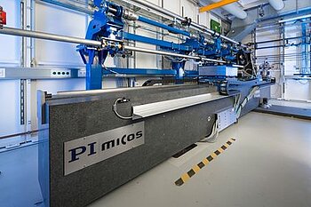
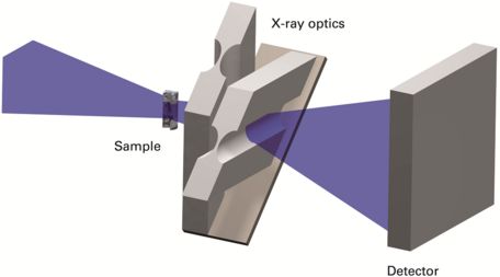
The full experimental instrumentation setup of nanotomography is based on a 6.8 m long granite bench to minimize the influence of vibrations, topped by four individually moving platforms for sample and detector stages and X‑ray optics for imaging or cone beam configurations moving platforms for sample and detector stages and X‑ray optics for imaging or cone beam configurations.
The substructure itself, which weighs several tons, is also on air bearings. This allows the entire assembly to be moved out of the X‑ray beam with minimal effort when the second experimental station is to be used, while maintaining a stable position as soon as the air flow is switched off.
All moving platforms are themselves mounted on air bearings and driven by linearmotors. This allows fast and precise positioning of all components.
A Complex Task: Positioning the Sample with Nanometer Precision
A particular challenge was the construction of the sample stage, since it had to be mechanically stable in the range below 100 nm, in order to achieve the required spatial resolution. To this end, several positioning systems have to work hand in hand with maximum precision, to ensure that always the same volume element is investigated when the sample is rotating.
The basis of sample positioning is a horizontal positioning unit which moves the sample stage into the beam. It has a travel range of 20 mm, can be subjected to a load of 300 kg and works with a repeatability of 30 nm. This high-precision positioning unit is equipped with stepper motors, precision crossed roller guidings and high-resolution optical linear encoders. Combined with the adequate motion controller, this allows closed-loop step sizes of a few nanometers.
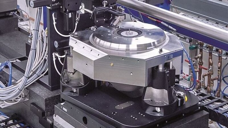
Height adjustment is done with three lifting elements that are also responsible for tilt correction and orthogonal alignment relative to the beam. It is based on three identical, symmetrically arranged, and position-controlled stepper motors, combined with worm gears and spindle drives. Mounted on this Z stage is an air-bearing supported rotation stage. In developing this stage, the designers had to go push the limits of technical feasibility: What was required was a really "pure" rotary motion of the sample with minimal wobble, radial runout or eccentricity. Only in this case can sharp pictures over 360 degrees be made which all refer to the same volume element and can all be clearly assigned when reconstructing the picture. This is why the rotation stage, which rotates at a velocity of 36 °/s, works with flatness deviations of less than 100 nm at a resolution of 0.5 µrad. The air bearing does not produce any friction, which over time would lead to a deterioration of these values.
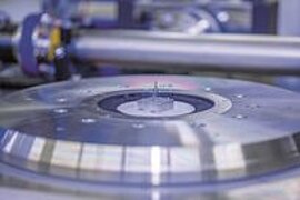
The actual sample holder is located in the aperture of the rotation stage on the moving platform of a six-axis parallel kinematic SpaceFAB robotics machine. Essential features are the freely selectable pivot point of the parallel-kinematic system and its high stiffness.
The SpaceFAB clearly makes work easier for the researchers, since the small samples – only a few 10 to 100 micrometers in size – plus the holder can initially be inserted into the stage with low precision. They can then be aligned automatically using software commands, not requiring any additional mechanical components for correct alignment.
A six-axis parallel-kinematic machine of this type is also used for the positioning of the X-ray where compound refractive lenses (CRL), which were developed at the Institute of Microstructure Technology (KIT, Karlsruhe), Germany, are in use.


