Machine builders use motorized stages to achieve precise positioning and movement for numerous manufacturing applications, including semiconductor production, additive manufacturing (3D printing), and the automotive industry. These motion systems play critical roles in tasks such as applying glue, performing inspections, and conducting lithography. Motion control systems can create an ideal trajectory for each task, defined by a series of set points to ensure smooth, optimized movements.
However, factors such as mechanical limitations, friction, or compliance can cause the actual motion path to deviate from this planned trajectory, creating what is known as a “following error.” Motion systems must therefore correct for these deviations by continuously comparing the actual and intended positions, making adjustments as needed (see Figure 1). This feedback loop, which can be achieved with various types of encoders, allows motion platforms to maintain high precision despite high dynamic load conditions or environmental changes.
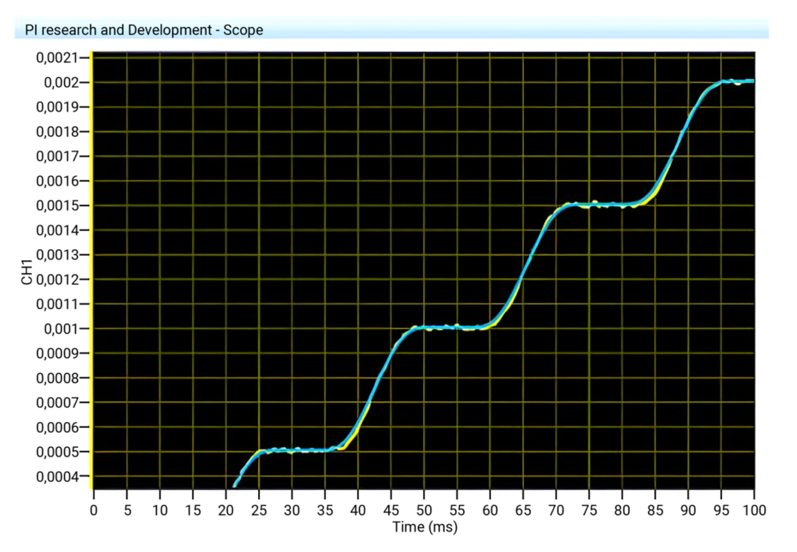
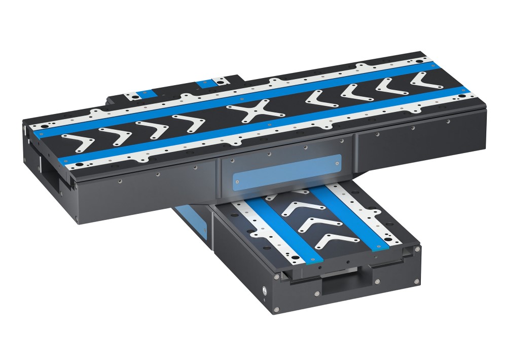
Figure 1: PI V-551 linear stage with a PIOne linear encoder, showing the blue trace as the ideal trajectory and the yellow trace as the actual motion path
Encoder Types
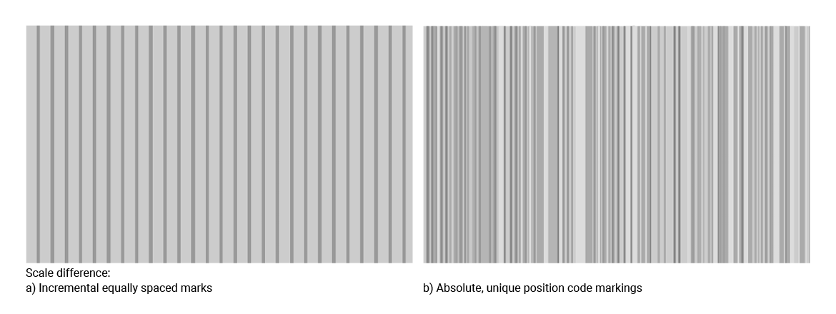
An encoder is a sensor that converts mechanical movement into an electrical signal, which is then relayed to the control system to give information about parameters such as position and velocity. Traditional encoders can be primarily categorized into incremental and absolute types (see Figure 2). Incremental encoders track relative position changes, continuously feeding data to the control system. In contrast, absolute encoders provide instant position feedback, eliminating the need for a homing process. This is particularly valuable in long-travel applications, as a machine might need to move a significant distance to find its zero point with an incremental encoder. Absolute encoders also have advantages in terms of system reliability, reducing the need for extensive wiring and improving the safety and speed of the start-up. However, incremental encoders offer other benefits, such as real-time feedback, lower cost, and high noise immunity, making them ideal for applications requiring continuous position updates without the complexity or expense of absolute encoders.
Signals
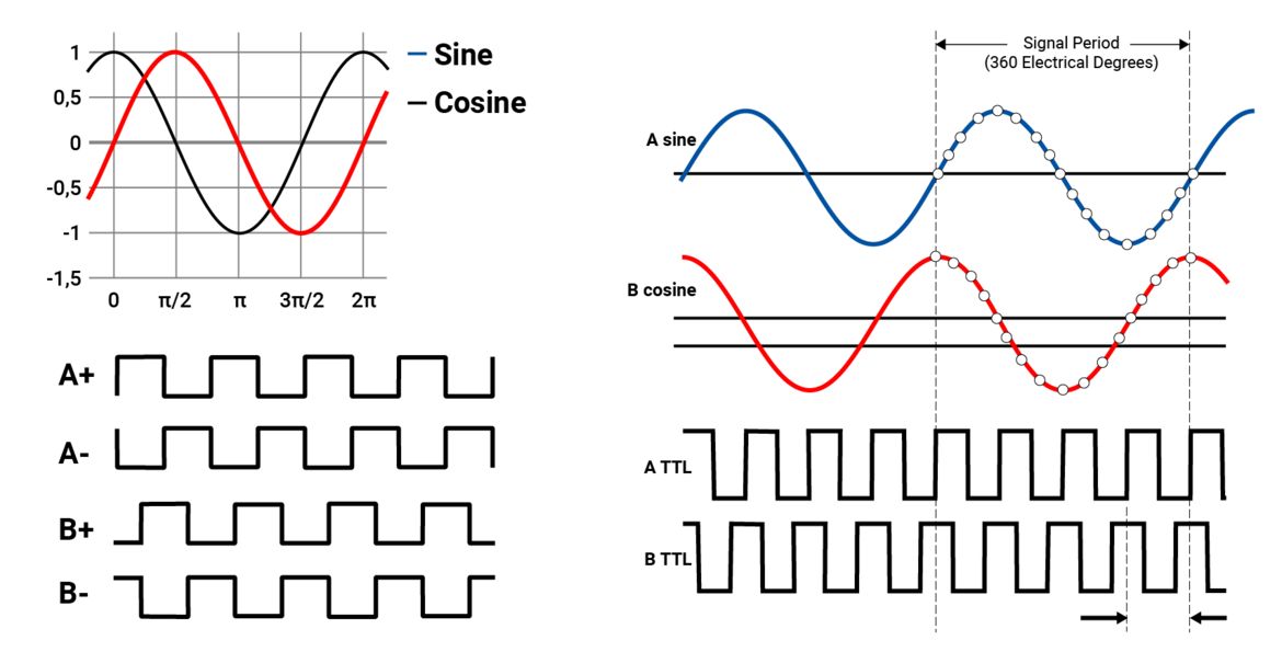
Incremental encoders typically output A quad B signals, which are widely compatible with motion control systems and provide good noise immunity (see Figure 3). Quadrature signals are two square waves offset by 90 degrees, allowing the system to track direction and position changes in a simple way. However, sine/cosine signals can offer higher resolution through interpolation. Sine and cosine signals are analog waveforms generated by encoders to represent position data. Sine signals provide high resolution but may be prone to signal noise, while cosine signals stabilize and validate the sine signal for more precise readings. To use sine/cosine signals with quadrature-based control systems, an interpolator is needed to convert the analog sine/cosine waves into a higher frequency quadrature signal, though often at a lower resolution than the full capability of the sine/cosine encoder. Absolute encoders, in contrast, generally use protocols such as BiSS-C and EnDat, which send data in serial form and on demand. This works well for precise, on-request data, but is less compatible with devices requiring continuous or real-time position updates, as absolute encoders only send position data when requested.
Synchronization with External Devices
In most applications, the motion of the stage must be synchronized with external devices such as lasers, cameras, and glue dispensers. A camera, for example, might need to capture an image at a precise position, or a glue dispenser may need to apply adhesive at exact intervals. Synchronization typically requires a physical trigger signal based on encoder information, which can be challenging with sine/cosine and absolute encoders. Incremental encoders with quadrature signals are therefore often preferred because they provide continuous position data. However, these encoders can be limited by resolution and are susceptible to signal noise in high-speed applications, as the signal bandwidth may be exceeded, causing data dropouts and positional inaccuracies.
Virtual Encoders
Although traditional A quad B incremental encoders are widely used in motion control, they are limited in more complex set-ups, such as gantry systems with two axes that work together. In these configurations, a “virtual cog” or center of gravity axis may be needed. Unfortunately, standard A quad B encoders cannot directly support these solutions, since they provide signals for each axis individually, rather than with respect to a unified central position. On the other hand, absolute encoders offer precise positioning, but don’t update continuously, making them unsuitable for real-time applications.
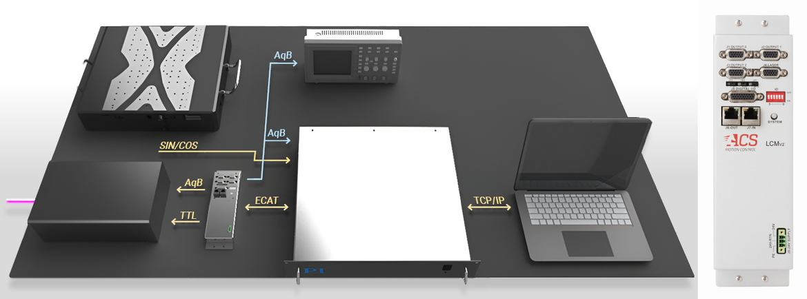
These limitations have led to the development of virtual encoders that rely on a calculated motion profile, which the controller tells the motor to follow. They create virtual A quad B signals based on the intended trajectory, instead of using physical encoder signals embedded in the stage. Virtual encoding uses laser control module (LCM) technology, where a high frequency clock generates accurate A quad B signals to synchronize with external devices to perform actions like dosing or triggering during constant motion (see Figure 4). This solution helps to maintain precise synchronization and eliminates challenges related to the physical encoder limits, allowing the system to output continuous, high resolution position data. This approach has been thoroughly tested in various applications, including additive manufacturing and precision inspection, showing that virtual encoders can be accurately programmed to closely follow motion profiles at high speeds and fine resolutions. Machine builders can greatly benefit from this technology in precision manufacturing applications, simplifying setup complexity while enhancing performance, synchronization, and resolution.